Overview
The Romi robot uses a layered control architecture that builds progressively from open-loop motor actuation to closed-loop velocity control and finally to high-level line-following behavior. Control design focused on achieving stable, repeatable motion rather than maximizing raw speed, allowing the robot to behave predictably across different operating conditions and battery states.
This page highlights the evolution of the motor control system and the final closed-loop structure used during line-following operation.
Motor Modeling and System Identification
Initial motor characterization was performed using open-loop effort tests to establish approximate system gain and time constant. These tests provided insight into motor dynamics and informed early controller tuning.
Open-loop data was used to estimate:
- Steady-state velocity versus applied effort
- Approximate motor time constant
- Relative left/right motor behavior
These results guided the selection of initial proportional gains before transitioning to closed-loop control.
Velocity Measurement Improvements
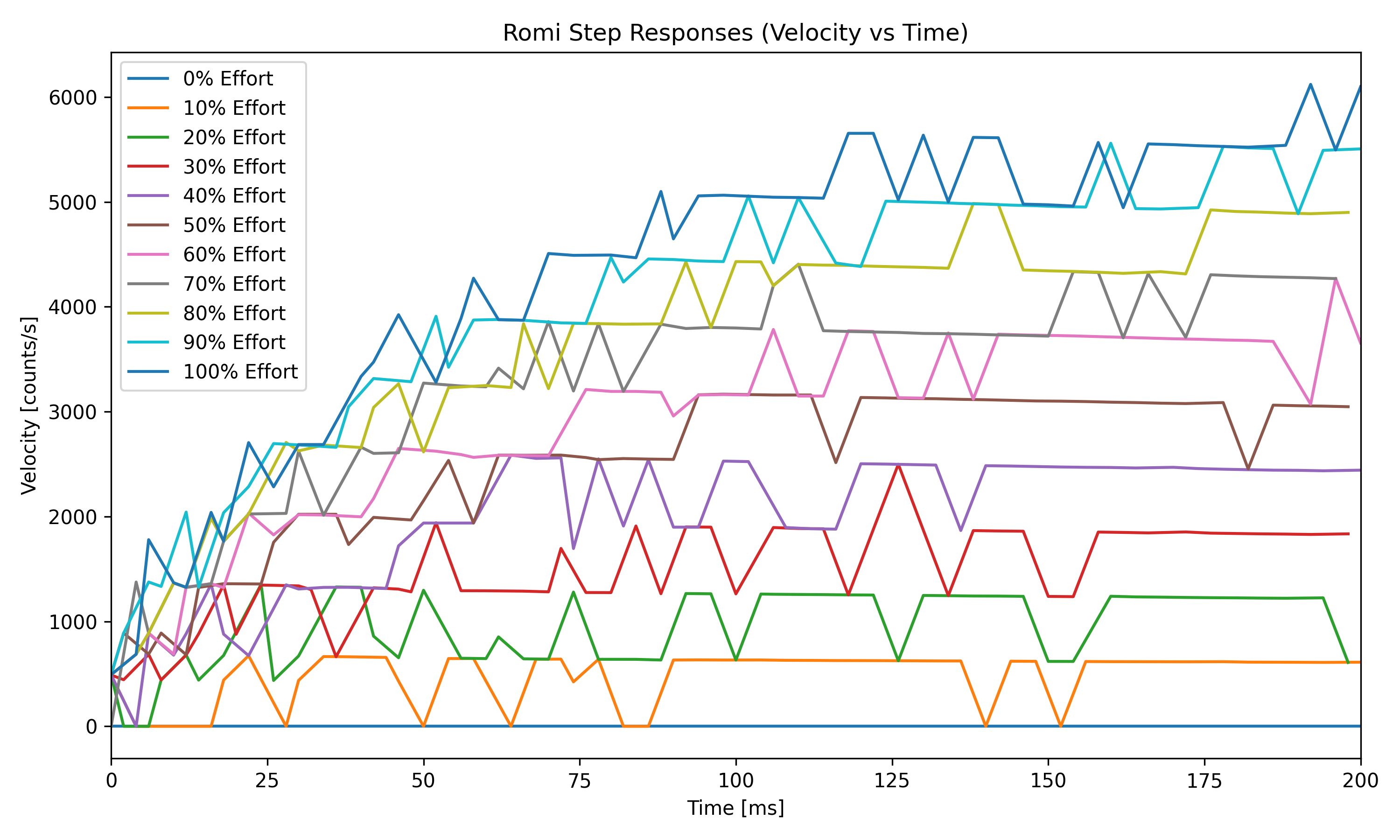
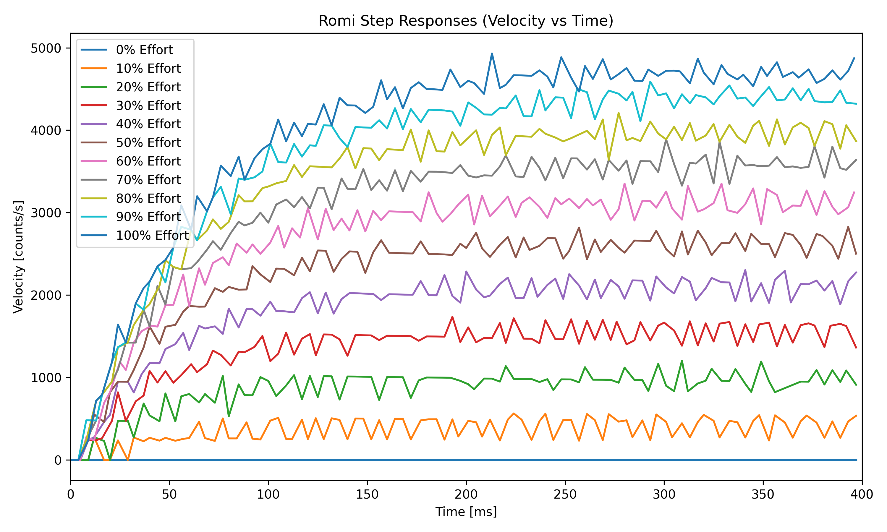
Early velocity measurements derived from encoder counts exhibited significant noise due to short sampling intervals and quantization effects. Several improvements were made to address this:
- Increased the motor control task period to improve measurement resolution
- Revised encoder velocity calculations to reduce numerical noise
- Ensured consistent timing between successive encoder reads
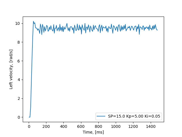
The progression below shows the improvement in velocity signal quality across successive step-response tests.
Closed-Loop Velocity Control
Closed-loop velocity control was implemented using a proportional–integral (PI) controller operating on each wheel independently. Encoder feedback provides continuous velocity measurements, allowing the controller to reject disturbances and track commanded setpoints more consistently than open-loop control.
Controller tuning was performed empirically by evaluating step responses across a range of gains and setpoints. Gains were selected to balance responsiveness with stability while avoiding excessive overshoot or oscillation.
Effect of Proportional and Integral Gains
To better understand controller behavior, individual proportional and integral gains were intentionally exaggerated during testing. These experiments revealed how each term influences responsiveness, stability, and steady-state behavior.
High Proportional Gain (Kp)
Increasing the proportional gain significantly improved rise time and reduced steady-state error. However, excessively high Kp values caused oscillatory behavior as the controller over-corrected for small velocity errors.
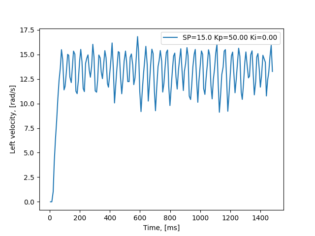
This oscillatory behavior reflects the controller reacting too strongly to measurement error and quantization effects in the encoder-derived velocity signal. Although tracking performance improved, stability was compromised.
Integral Gain Effects (Ki)
Integral gain was introduced to reduce steady-state error and improve long-term setpoint tracking. When Ki was increased excessively, the controller exhibited a gradual upward drift in velocity as accumulated error continued to drive the output.
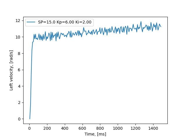
This behavior highlights the tradeoff between eliminating steady-state error and maintaining bounded control action, particularly in the presence of sensor noise and timing variability.
Cascaded Control Structure
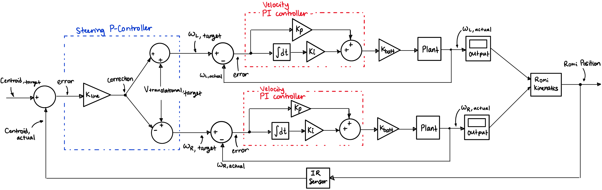
Line following is implemented using a cascaded control structure. An outer loop interprets reflectance sensor measurements to generate a steering correction, while inner velocity loops regulate individual wheel speeds.
This separation allows the line-following logic to operate independently of motor dynamics and improves robustness to disturbances such as curvature changes or brief sensor dropout.
Discussion
Implementing closed-loop velocity control significantly improved the robot’s repeatability and predictability. Improvements to encoder velocity estimation were critical; controller performance was ultimately limited more by measurement quality than by controller structure.
This layered approach simplified debugging and allowed individual components of the system to be validated independently before full integration with line-following behavior.